|
|
|
![]()
![]()

![]()
Usually, any tools or handling devices of a manipulator can be described with the help a constant homogeneous transformation, if related to the last, outmost link of the robot.
In this tool frame, environmental objects can be easily located relative to the tool tip or gripper. To achieve the related joint motion to move the tool tip appropriately, the necessary motion trajectory of the tip with respect to the base frame has to be calculated. The resulting base frame description can then be used to solve the inverse kinematics problem, that is to find the related joint coordinates.
Let assume, an industrial manipulator with 6 revolute joints:
|
|
Joint variables (actual arm posture) |
|
|
constant Denavit-Hartenberg parameters |
|
|
Tool frame, described in the |
|
|
coordinate frame system of the outmost link |
The homogeneous transformation relating the tool frame to the fixed base frame is given by:
|
|
(2.12) |
This equation shows the complete homogeneous transformation, that transforms
the position and orientation of the tool through the kinematic chain towards the
Cartesian base frame. This transformation depends on actual joint positions,
which are included as variant Denavit-Hartenberg parameters into all individual
link transformations
![]() .
.
The joint positions ![]() ,
which describe the posture of the robot definitively, are called joint
coordinates. The above equation transforms them into a Cartesian (base)
frame, a procedure called direct kinematics problem or forward
kinematics problem.
,
which describe the posture of the robot definitively, are called joint
coordinates. The above equation transforms them into a Cartesian (base)
frame, a procedure called direct kinematics problem or forward
kinematics problem.
It is immediately clear, that a definitive solution to the direct kinematic problem can be obtained for arbitrary joint positions, joint configurations and any number of joints. It is helpful to have a notation such as the Denavit-Hartenberg notation available, which allows a very systematic treatment of kinematic descriptions and homogeneous transformations.
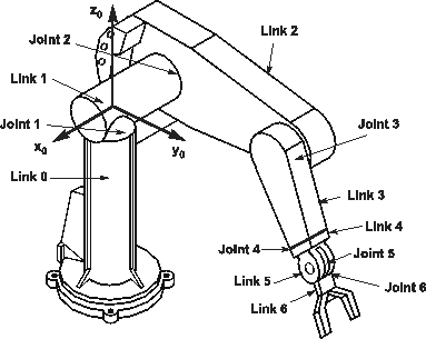
The solution of the direct kinematics problem is now explained for an industrial robot with 6 joints, which is thePUMA 562 robot.
Figure 2.9 shows the robot with its joints and links. The figure immediately following presents the robot with its different frame locations.
|
|
|
Figure 2.9: PUMA industrial robot with 6 revolute joints |
The link frame assignment for the PUMA 562 is presented according to DH-notation in figure 2.10.
|
|
|
Figure 2.10: DH frame assignment for the PUMA robot |
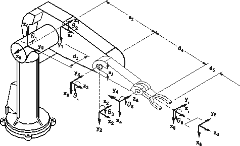
The location of DH-frames and DH-parameters is shown in figure 2.11. where the 'zero' position for the PUMA joints is assumed.
|
|
|
Figure 2.11: PUMA frames in joint 'zero' position |
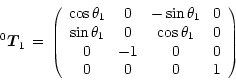
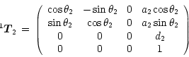
Transformations between all neighboring frames are given by the following DH-transformations:
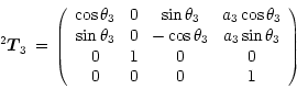
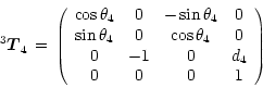
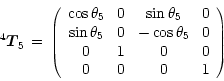
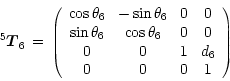
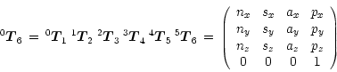
Multiplication of these matrices leads to the complete transformation from tool frame towards base frame, which solves the direct kinematics problem:
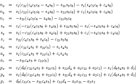
The following abbreviations have been used here:
![]() ,
,
![]() ,
,
![]() and
and
![]() .
.