|
|
|
![]()
![]()
In order to find a transformation from tool tip to the base of a manipulator,
we have to define link frames and to derive a systematical technique, which
allows to describe the kinematics of a robot with
![]() degrees
of freedom in a unique way. A set of
degrees
of freedom in a unique way. A set of
![]() parameter
will turn out to be sufficient for that purpose.
parameter
will turn out to be sufficient for that purpose.
|
|
|
Figure 2.7: Links of a kinematics chain |
Figure 2.7 presents the first links of a kinematics chain. The base and each
link ![]() of
the chain is assigned to a specific frame
of
the chain is assigned to a specific frame
![]() ,
which is fixed to the link. So the position and orientation of a link frame
changes with respect to a neighboring link frame according to the motion of
their connecting joint. Therefore coordinate frame
,
which is fixed to the link. So the position and orientation of a link frame
changes with respect to a neighboring link frame according to the motion of
their connecting joint. Therefore coordinate frame
![]() can
be described from its precedent link frame
can
be described from its precedent link frame
![]() by
means of a homogeneous transformation. This homogeneous transformation includes
the joint angle (for rotary joints) or the joint offset (for prismatic joints).
by
means of a homogeneous transformation. This homogeneous transformation includes
the joint angle (for rotary joints) or the joint offset (for prismatic joints).
Finally the tool frame ![]() can
be transformed to the base frame by multiplication of all the link
transformations through the kinematic chain. So in order to transform any
position/orientation relative to the tool frame (e.g. by sensorics attached
there) towards the manipulators base frame (e.g. where it is fixed to the
floor), the sorted sequence of homogeneous transformations from tip to toe via
can
be transformed to the base frame by multiplication of all the link
transformations through the kinematic chain. So in order to transform any
position/orientation relative to the tool frame (e.g. by sensorics attached
there) towards the manipulators base frame (e.g. where it is fixed to the
floor), the sorted sequence of homogeneous transformations from tip to toe via
![]() has
to be processed. The remaining task is to set up all the homogeneous
transformation matrices for a particular type of kinematic chain, considering
geometrical attributes of link arrangements and types of joints.
has
to be processed. The remaining task is to set up all the homogeneous
transformation matrices for a particular type of kinematic chain, considering
geometrical attributes of link arrangements and types of joints.
|
|
|
Figure 2.8: Assignment of DH-parameters |
Figure 2.8 shows a detail of a kinematic chain, where two links are connected via a rotary joint. It is used to show, how invariant parameters are obtained which describe a link.
The axes of rotation for link ![]() and
and
![]() are
extended towards straight lines
are
extended towards straight lines ![]() ,
,
![]() ,
which in general are warped with respect to each others. The straight lines
,
which in general are warped with respect to each others. The straight lines
![]() and
and
![]() have
a common normal line
have
a common normal line ![]() ,
which is perpendicular to both of them. The point of intersection
,
which is perpendicular to both of them. The point of intersection
![]() between
straight line
between
straight line ![]() and
normal line
and
normal line ![]() is
defined as origin of link frame
is
defined as origin of link frame ![]() .
Further on, the base vector
.
Further on, the base vector
![]() is
defined as extension of the normal line, whereas the base vector
is
defined as extension of the normal line, whereas the base vector
![]() of
this link frame is assumed to be matching the straight line
of
this link frame is assumed to be matching the straight line
![]() and
thereby describing the axis of rotation for link
and
thereby describing the axis of rotation for link
![]() .
Now given the vectors
.
Now given the vectors
![]() and
and
![]() ,
the remaining base vector of this frame
,
the remaining base vector of this frame
![]() is
chosen appropriately in order to create a right-hand coordinate frame.
is
chosen appropriately in order to create a right-hand coordinate frame.
Let us assume that the same operation has already been carried out for the
precedent links. In this case, coordinate frame
![]() is
determined with its origin
is
determined with its origin ![]() located
on straight line
located
on straight line ![]() .
.
We are now able to derive some necessary parameters for link description.
Parameter ![]() is
already introduced, whereas the second characteristic parameter
is
already introduced, whereas the second characteristic parameter
![]() is
defined here as distance between origin
is
defined here as distance between origin
![]() of
frame
of
frame ![]() and
the intersection
and
the intersection ![]() of
normal line
of
normal line ![]() (but
this time) with straight line
(but
this time) with straight line ![]() .
.
Obviously the origin of frame ![]() is
located in the plane, which is stretched out by the pair of joint rotation
vectors
is
located in the plane, which is stretched out by the pair of joint rotation
vectors
![]() and
and![]() .
One more characteristic link parameter is the angle
.
One more characteristic link parameter is the angle![]() ,
which occurs between both joint rotation vector
,
which occurs between both joint rotation vector
![]() and
and![]() .
.
For link ![]() ,
the rotation of its rigid body
,
the rotation of its rigid body ![]() (with
respect to its rigid body
(with
respect to its rigid body ![]() )
is given by the rotation angle
)
is given by the rotation angle ![]() .
In other words, angle
.
In other words, angle ![]() is
located between
is
located between
![]() -axis
and
-axis
and
![]() -axis.
-axis.
For revolute joints, joint parameters
![]() und
und
![]() are
constant. They depend on joint design only and do not include any joint motion.
The only variant parameter for revolute joints is the angle
are
constant. They depend on joint design only and do not include any joint motion.
The only variant parameter for revolute joints is the angle![]() ,
which describes variable joint positions.
,
which describes variable joint positions.
The situation is different for prismatic joints. Here parameter
![]() becomes
variable and describes translational joint positions, whereas parameters
becomes
variable and describes translational joint positions, whereas parameters
![]() und
und
![]() depend
on joint design only.
depend
on joint design only.
However, in principle prismatic and revolute joints can be completely described with just 4 parameters:
|
|
Length of normal line
|
|
|
Angle between
|
|
|
Length of line
|
|
|
Angle between
|
A homogeneous transformation
![]() mapping
frame
mapping
frame ![]() towards
towards
![]() via
the actual link, can be derived now from the following geometrical
transformations via the link under consideration:
via
the actual link, can be derived now from the following geometrical
transformations via the link under consideration:
|
1. |
Rotation around
|
|
2. |
Translation along
|
|
3. |
Translation along
|
|
4. |
Rotation around
|
or, in a more formal description with the help of homogeneous transformation matrices for each of the 4 actions mentioned above:

, which leads to the following general description of transformations via prismatic or revolute joints:
|
|
(2.11) |
Apparently homogeneous link transformations
![]() become
especially simple, if the angular parameter
become
especially simple, if the angular parameter
![]() is
set to some specific values, which are multiplicities of
is
set to some specific values, which are multiplicities of
![]() .
As parameter
.
As parameter ![]() is
always constant, no matter whether a prismatic or a revolute joint is
considered, simplifying the link transformation can be done through joint
construction. From the physical viewpoint,
is
always constant, no matter whether a prismatic or a revolute joint is
considered, simplifying the link transformation can be done through joint
construction. From the physical viewpoint,
![]() becomes
a multiplicity of
becomes
a multiplicity of![]() ,
if neighboring axis are in parallel or perpendicular to each others.
,
if neighboring axis are in parallel or perpendicular to each others.
In fact, most of the industrial robots are designed according to these considerations. Observing this construction rule does in no way restrict any practical demands on the robot. Thereby some necessary calculations are facilitated for the robot controller, for example transformations from cartesian task descriptions to joint motion interpolation, and vice versa.
One more practical demand for robot design has to be mentioned here:
There is one posture of the robot arm (of its open kinematic chain), where all the joints are in 'zero' position. This posture itself is called the arms' zero position. Usually it is a reference position for measurement of joint positions by internal sensorics. Therefore the posture should be physically accessible for the robot.
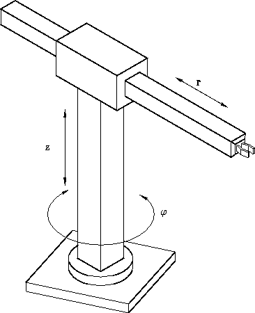
Consider the classical cylindrical robot, which means this type of robot
moves in radial, angular and vertical components due to the special arrangement
of robot joints.
There is a translational joint for radial motion, a revolute joint for angular
motion and another translational joint for vertical motion available.
This special arrangement gives 3 cylindrical degrees of freedom.
The robot is presented in figure
3.3. Note that the robot has a minimum radial
component of value
![]() .
.
 |
Task:
Find the forward transformation of the cylindrical robot via
Denavit-Hartenberg frame assignments, thus relating joint positions
![]() to cartesian positions in the robots base frame
to cartesian positions in the robots base frame
![]() .
.
Solution:
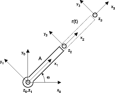
According to the previously introduced frame assignment concept we define 4 different frames for the given cylindrical robot:
 |
Transformation between these frames is based upon the general transformation
description given above.
The individual transformations between neighboring frames are as follows:
![]()

![]()

![]()

Thus the resulting transformation between tool frame
![]() and the
base frame
and the
base frame
![]() is given by
is given by
![]() :
:
![]()
The complete notation is:

Observing the motion of frame
![]() itself in
cartesian space, set
itself in
cartesian space, set
![]() .
.
This frame moves in 3D space with the following dependencies on joint motions
![]() :
:
![\begin{eqnarray*}
x_0 (t) & = & [A+r(t)] \cos \Theta_1 \\
y_0 (t) & = & [A+r(t)] \sin \Theta_1 \\
z_0 (t) & = & d_z(t) \\
\end{eqnarray*}](img174.gif)