|
|
|
![]()
![]()
We return to the description of general locations (position and orientation)
in 3D space. As a result of our previous considerations we have found it
sufficient in order to describe locations, that we apply a position vector
![]() to
describe translations with respect to a reference frame, and an orientation
matrix
to
describe translations with respect to a reference frame, and an orientation
matrix
![]() to
describe rotations.
to
describe rotations.
Figure 2.5 assumes, that the location of a cube is available via position
vector and orientation matrix. Position ![]() of
the corner opposite to the bodies frame
of
the corner opposite to the bodies frame ![]() is
known relative to the body frame via
is
known relative to the body frame via
![]() .
.
|
|
|
Figure 2.5:
Body position |
With respect to the universal frame
![]() ,
the position of
,
the position of ![]() is:
is:
![]()
The given result is achieved by simple addition of vectors
![]() and
and
![]() .
.
This procedure can be easily extended to describe more complex relations between frames.
|
|
|
Figure 2.6: Series of homogeneous transformations |
Figure 2.6 shows the derivation of a position vector
![]() ,
where position
,
where position ![]() is
known relative to frame
is
known relative to frame ![]() .
All the frames are related via a position offset between their origins, which is
described by vectors
.
All the frames are related via a position offset between their origins, which is
described by vectors
![]() and
and
![]() .
.
![]()
Alternatively it can be calculated:
![]()
This equation can be reduced in a very handsome way by introducing homogenous coordinates and transformation.

A closer look shows the benefits of this notation:
Position vector
![]() has
been extended here with a forth coordinate of constant value
has
been extended here with a forth coordinate of constant value
![]() .
.
This enlarged presentation of a position is called homogeneous coordinates
notation. The homogeneous transformation matrix
![]() includes
all necessary information about the position and orientation of a reference
frame with respect to another frame.
includes
all necessary information about the position and orientation of a reference
frame with respect to another frame.
In homogeneous representation the previous equation becomes:
![]()
Obviously the mapping of frame ![]() towards
frame
towards
frame ![]() is
accomplished by a simple multiplication of individual transformations.
is
accomplished by a simple multiplication of individual transformations.
![]()
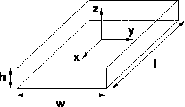
Consider the homogeneous rectangular beam of mass
![]() , length
, length
![]() , width
, width
![]() and height
and height
![]() , as
presented in figure
5.3.
, as
presented in figure
5.3.
 |
There is a homogeneous distribution of mass density in the beam, which means:
![]()
As shown, this define a body frame in the center of mass of the beam, and arrange the coordinate axes according to the principal axes of the beam.
To find the moments of inertia and set up the corresponding inertia tensor
follow the rules presented above. The moment of inertia with respect to the
![]() -axis of the
frame becomes:
-axis of the
frame becomes:
![]()
This leads to:
![]()
The same calculation applies for the moments of inertia
![]() und
und
![]() .
.
Finally let us consider moments of deviation, for example in
![]() and
generalize the result for all other moments of deviation.
and
generalize the result for all other moments of deviation.
![]()
conclude:

The same result applies for all other moments of deviation.
Now can set up the inertia tensor:
![\begin{displaymath}
{\cal I} \; = \;
\left[
\begin{array}{ccc}
\frac{m}{12} (w^2...
... & 0 \\
0 & 0 & \frac{m}{12} (w^2 + h^2)
\end{array}\right]
\end{displaymath}](img294.gif)